
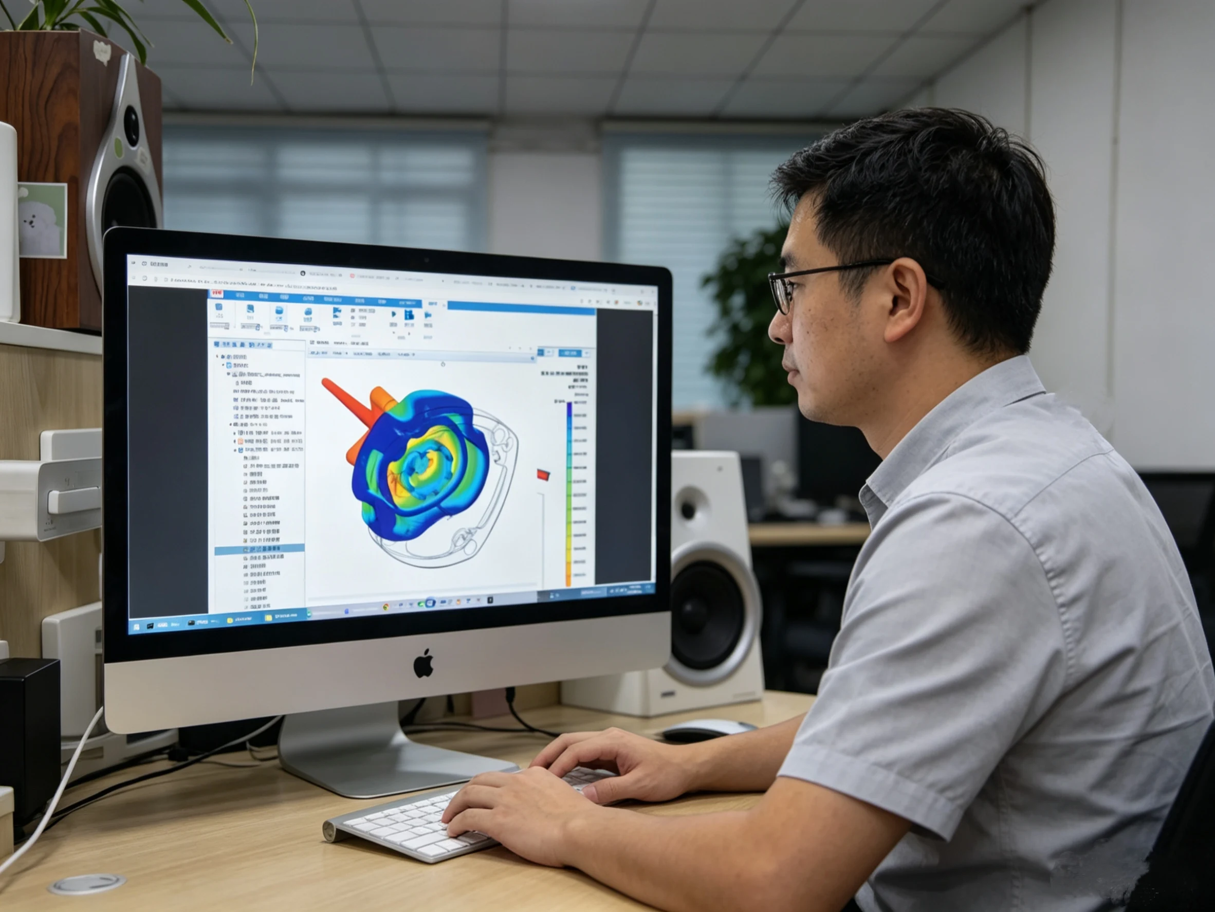
Many die-casting decisions become expensive after the tool design is released. Gate locations, runner sections, overflows, vents, cooling lines, slides, and local wall thicknesses are connected. A change made after steel is cut can affect several of these features at once, and a late correction may require design work, tool modification, another trial, and a new validation review.
Mold flow analysis gives the engineering team a way to compare plausible manufacturing routes before those decisions become difficult to change. It can show how a metal front is expected to move, where fronts meet, where air may be trapped, how temperature evolves, where solidification may be delayed, and where the predicted part may distort after ejection. These outputs help the team ask better questions about the part and die design.
The model is still a model. A colorful result does not prove that a physical die will fill exactly as shown, that a casting will meet a drawing, or that a production process has been validated.
1. What a die-casting CAE model is trying to describe
Filling: how the metal front moves through the cavity
A filling analysis follows the expected movement of molten metal through the shot system, runner, gates, and cavity. The team can review fill time, meeting fronts, hesitation, jetting, areas that fill last, and the sequence in which functional features are reached. These observations are useful when comparing a gate location or checking whether a thin section is likely to fill before the metal loses too much heat.
The objective is not simply to make the shortest fill time. A fast front can still create an unfavorable flow pattern if it impinges on a core, folds across a feature, or leaves a final-to-fill region without a suitable evacuation path. Filling should be read together with air movement, temperature, and the intended overflow and vent arrangement.
Pressure and packing: what happens after the cavity fills
After the cavity is filled, pressure transfer and intensification affect the way the casting responds while solidification continues. A simulation may compare pressure-related assumptions, local solidification behavior, and likely shrinkage-sensitive regions. The exact interpretation depends on the machine, die, alloy, and process inputs represented by the model.
Pressure is not a universal remedy for every discontinuity. If the filling pattern has already trapped air, adding pressure may not remove the underlying cause. If a section has solidified before effective pressure transfer, a nominal pressure value does not guarantee feeding or soundness. The analysis should connect pressure assumptions to the filling sequence and solidification evidence.
Cooling and solidification: where thermal balance changes the outcome
Cooling analysis examines how heat leaves the metal and the die. Wall thickness, ribs, bosses, inserts, die temperature, cooling-channel assumptions, spray or lubrication conditions, and local heat extraction can create different thermal histories across the part. A region that remains hot longer may become a last-solidifying area or a source of cycle-to-cycle instability.
Warpage: predicted deformation after release and ejection
Warpage analysis estimates how a part may move as it cools and as constraints are released. Uneven shrinkage, temperature differences, section changes, ribs, bosses, inserts, and ejection conditions can all influence the predicted shape. The result is best treated as a comparison between design or process options, not as a guaranteed dimensional report.
2. Four risk questions that should be read together
Mold flow analysis becomes more useful when the results are not reduced to one pass/fail image. A review normally separates several questions:
- Filling sequence: Does the metal reach each region in an intended order, without unnecessary hesitation, jetting, or harmful impingement?
- Air entrapment: Where is displaced air expected to collect, and do overflows, vents, or vacuum features provide a credible path?
- Solidification and shrinkage: Which regions remain liquid longest, and do geometry, pressure assumptions, and thermal balance make them sensitive to internal discontinuities?
- Thermal balance and warpage: Are local temperatures and cooling assumptions likely to create deformation, ejection, or dimensional risks in critical zones?
These questions interact. Moving a gate can change the fill sequence and the last-to-fill location. Changing an overflow can change both evacuation and the amount of metal entering a region. Changing cooling can move a hot spot and alter predicted deformation. A useful review records the design decision associated with each result instead of treating the simulation report as an isolated picture.
3. Input quality determines output usefulness
Geometry and revision control
The model should start from the correct part revision and a clearly identified die concept. Parting direction, draft, wall sections, ribs, bosses, inserts, slides, machining allowance, gates, runners, overflows, vents, and cooling features should be represented at the level needed for the question. A result based on an outdated CAD revision can be technically consistent and still be irrelevant to the released design.
Material and thermal data
Alloy selection affects density, viscosity, thermal conductivity, heat capacity, solidification behavior, and shrinkage assumptions. Melt temperature and die temperature also influence the predicted flow and thermal history. Generic material data may be useful for an early comparison, but it should not be presented as the confirmed condition for a specific program.
Gating, overflow, venting, and vacuum assumptions
Gate location and section influence velocity, meeting fronts, and the last-to-fill regions. Overflows and vents define where displaced air and the first material may go. Vacuum features introduce additional assumptions about evacuation and leakage. These details are part of the question being simulated, not decoration around the model.
Machine and process inputs
Shot profile, switching point, intensification timing, pressure, cycle assumptions, melt temperature, die temperature, lubrication, and cooling conditions can materially change the result. The report should state which inputs are measured, which are estimated, which are held constant, and which are being compared.
4. A practical workflow: from a risk map to a better die concept
- Define the engineering question before running the model: start with the part function, the critical zones, and the decision that is still changeable.
- Establish a baseline concept using the current part revision, proposed gating, overflow and vent arrangement, cooling assumptions, material data, and process inputs.
- Trace a suspected stagnation or air-trap path by reviewing the local metal-front sequence, expected air-trap location, and available overflow or vent path.
- Compare a targeted revision, such as a gate, runner, overflow, vent, or local-feature change, while keeping the changed variable clear.
- Review unintended effects, including moved meeting fronts, changed hot spots, flash exposure, trim design, and cooling access.
- Carry the prediction into the die trial by defining observations, process records, and physical inspection needed to confirm or challenge the model.
Suppose the baseline shows a late-filling pocket near a functional feature. The team can inspect the local metal-front sequence, expected air-trap location, and available overflow or vent path. The relevant question is not only whether the color plot looks unfavorable, but whether the die concept gives displaced air somewhere to go before the metal front closes the path.
The output should become a design decision record: selected concept, rejected alternatives, remaining assumptions, critical zones, and physical checks required at trial. If the trial differs from the prediction, investigate the input and boundary conditions before declaring the model or the process correct.
5. When should a project use mold flow analysis?
- Complex geometry and multiple competing flow paths: ribs, bosses, pockets, thin walls, inserts, slides, or several potential gates.
- Appearance-critical surfaces: filling and thermal balance may affect surface variation, meeting fronts, and local finishing risk.
- Structural, sealed, or machined features: connect flow and thermal risks to pressure boundaries, sealing faces, datums, threads, load paths, and interfaces.
- New-product introduction or a major design change: compare a new die concept, gate revision, wall-thickness change, alloy condition, or machine route before release.
- When analysis is not the right first step: clarify an unsettled CAD revision, unknown alloy, undefined critical zones, or an output that would not change a decision.
6. What simulation cannot replace
CAE simulation does not replace a die trial. A physical trial exposes the response of the actual machine, die, cooling circuit, lubrication practice, vents, overflows, melt, and operators under real conditions. Trial evidence can confirm, challenge, or refine the assumptions used in the model.
Simulation does not replace process records or dimensional, internal, leak, or functional inspection. A predicted low-risk region is not proof that a casting meets the drawing. The appropriate inspection method depends on the functional question and may include dimensional measurement, radiography, CT, sectioning, density comparison, leak testing, or another agreed method.
Simulation also does not establish a supplier's certification, machine capability, software ownership, capacity, lead time, or customer-specific acceptance. Those are separate project claims requiring written evidence.
7. A review checklist for an RFQ or tooling release
- Part and revision: current CAD, drawing revision, material requirement, and intended process route.
- Functional zones: sealing, pressure, load, appearance, machining, datum, thread, and interface areas marked on the drawing.
- Die concept: parting direction, proposed gates, runners, overflows, vents, vacuum assumptions, slides, inserts, and cooling concept.
- Process inputs: known or provisional melt and die temperatures, shot profile, switching point, pressure assumptions, and cycle conditions.
- Questions to answer: filling sequence, hesitation, air entrapment, hot spots, solidification, cooling balance, warpage, or a defined concept comparison.
- Decision and validation record: assumptions, alternatives, selected changes, remaining risks, trial observations, process records, inspection, and acceptance rules.
Conclusion: use CAE to move the right decisions earlier
Mold flow analysis can reduce uncertainty before tooling decisions become expensive by making the expected filling, air movement, thermal balance, solidification, and deformation easier to discuss. Its value comes from comparing defined concepts against the part's function and critical zones, not from treating a simulation image as a guarantee.
The strongest workflow is a chain: current CAD and drawing requirements, explicit inputs, baseline analysis, targeted design changes, review of unintended effects, physical trial, process records, and inspection. When those links are documented, CAE becomes useful evidence in a tooling decision without pretending to replace the evidence that only a physical part can provide.
Planning a new die-cast part or a tooling revision? Share the drawing, CAD revision, material requirement, critical zones, and the decision still open. Inox Precise can help frame the questions that need written technical confirmation before the die concept is released.
Reference starting points
- Autodesk Moldflow product overview and analysis context: https://www.autodesk.com/products/moldflow/overview
- North American Die Casting Association (NADCA), technical resources on die-casting process and quality questions: https://www.diecasting.org
- Project-specific drawing, CAD revision, material data, process window, trial record, inspection procedure, and customer acceptance criteria - to be supplied and approved in writing for the actual program.